Kamis, 10 Juni 2010
Minggu, 30 Mei 2010
SISTEM BASIS DATA (select di dalam select)
Ini adalah sebagian contoh soal yang dijalankan pada oracle XE
Terlebih dahulu kita membuat table- table nya dahulu, sbb :
iklim


3. Berapa jumlah harga bunga dimana bukan berdasarkan nama latih huruf tengah = "la"
jawab :

4. Tampilkan nama latin, iklim terendah dan iklim tertinggi dimana harga lebih besar sama dengan Rp 70000
jawab :


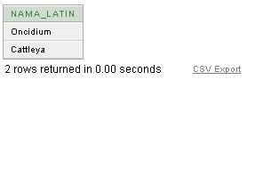
5. Tampilkan nama latin dimana bukan berdasarkan nama bunga berawalan huruf A
jawab :


6. Tampilkan kode kirim dan jenis kirim dimana kode kirim kurang dari 6 dan 7
jawab :


7. Tampilkan data-data semua dari table infoanggrek dimana bukan berdasarkan harga kurang dari Rp 60000
jawab :

 8. Tampilkan nama bunga yang kode anggrek = 301
jawab :

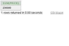
 9. Berapa jumlah harga dimana kode kirim "6"
jawab :

 10. Tampilkan nama bunga yang kode kirimnya = 6
jawab :


Terlebih dahulu kita membuat table- table nya dahulu, sbb :
iklim

pengiriman

infoanggrek

price

beberapa contoh soal select di dalam select, sbb :
1. Tampilkan kode bunga dan nama bunga dimana bukan berdasarkan jenis kirim BOTOL
jawab :
jawab :


2. Berapa rata-rata harga bunga dimana iklim tertinggi = 4 dan iklim terendah = 2
jawab :


3. Berapa jumlah harga bunga dimana bukan berdasarkan nama latih huruf tengah = "la"
jawab :


4. Tampilkan nama latin, iklim terendah dan iklim tertinggi dimana harga lebih besar sama dengan Rp 70000
jawab :


5. Tampilkan nama latin dimana bukan berdasarkan nama bunga berawalan huruf A
jawab :

6. Tampilkan kode kirim dan jenis kirim dimana kode kirim kurang dari 6 dan 7
jawab :


7. Tampilkan data-data semua dari table infoanggrek dimana bukan berdasarkan harga kurang dari Rp 60000
jawab :


jawab :

jawab :


jawab :


Kamis, 29 April 2010
OOP ( Object Oriented Programming )
OOP (Object Oriented Programming) atau Pemprograman berorientasi objek adalah suatu cara baru dalam berfikir serta berlogika dalam menghadapi masalah-masalah yang akan dicoba diatasi dengan bantuan komputer. OOP, tidak seperti pendahulunya (Pemprograman Terstruktur), mencoba melihat permasalahan lewat pengamatan dunia nyata dimana setiap objek adalah entitas tunggal yang memiliki kombinasi struktur data dan fungsi tertentu. Ini kontras dengan pemprograman terstruktur dimana struktur data dan fungsi didefinisikan secara terpisah dan tidak berhubungan secara erat.
http://www.digituck.com/konsep-oop-object-oriented-programming.html
http://www.digituck.com/konsep-oop-object-oriented-programming.html
http://www.digituck.com/konsep-oop-object-oriented-programming.html
Class Dan Atribut
Class adalah cetak biru atau rancangan dari sebuah object. Object adalah instansiasi atau perwujudan dari sebuah class, sebuah class dapat di instan menjadi satu atau lebih object, sebuah class tidak dapat digunakan untuk menyimpan, memanipulasi dan menampilkan data. Kita bisa melakukan proces-proses tersebut terhadap object.
Didalam class terdapat atribut atribut. Atribut adalah segala sesuatu yang berhubungan dengan objek. Misal didalam class rumah yang didalamnya maka atribut atributnya adalah kayunya, warnanya, pintunya, teras, luas dll.
Sedangkan Metohode adalah hal hal yang dapat dilakukan oleh class, dalam pemrogaman prosecural methode dapat diartikan sebagai f uction atau procedure. dalam contoh class rumah diatas, methodenya adalah tempat bernaung.
Package
Dalam rangka manajemen class, class-class yang secara fungsional sejenis bisa dikelompokkan kedalam suatu wadah atau kedalam suatu folder. ada banyak package bawaan java, sepeti java.awt, javax.swing. java.io, java.util. Namun demikian user diperbolehkan untuk membuat package sendiri. isi dari sebuah packagw adalah semua file class yang siap pakai.
Hak Akses
OOP memberikan beberapa tipe hak akses terhadap variable (atribut), methode bahkan class. Tipe tipe hak akses tersebut yaitu Public, Private, atau Protected. Ini adalah salah satu bagian terpenting dari OOP, sehingga programmer yang hendak belajar OOP wajib memahami konsep pengaksesan data ini dalam OOP.
Inheritance ( Pewarisan )
Inheritance (Pewarisan) merupakan salah satu dari tiga konsep dasar OOP. Konsep inheritance ini mengadopsi dunia riil dimana suatu entitas/obyek dapat mempunyai entitas/obyek turunan. Dengan konsep inheritance, sebuah class dapat mempunyai class turunan. Suatu class yang mempunyai class turunan dinamakan parent class atau base class. Sedangkan class turunan itu sendiri seringkali disebut subclass atau child class.
Dalam dunia riil, suatu entitas turunan dapat mewarisi apa-apa yang dipunyai dari entitas induknya. Misalkan saja antara entitas Bapak dan entitas Anak. Entitas anak dapat mewarisi apa-apa yang dipunyai oleh entitas Bapaknya. Demikian juga dalam konsep inheritance, suatu subclass dapat mewarisi apa-apa yang dipunyai oleh parent class. Inilah yang terpenting dari konsep inheritance.
Karena suatu subclass dapat mewarisi apa-apa yang dipunyai oleh parent class-nya, maka member dari suatu subclass adalah terdiri dari apa-apa yang ia punyai dan juga apa-apa yang ia warisi dari class parent-nya. Kesimpulannya, boleh dikatakan bahwa suatu subclass adalah tidak lain hanya memperluas (extend) parent class-nya.
Polimorfisme
melalui pengiriman pesan. Tidak bergantung kepada pemanggilan subrutin, bahasa orientasi objek dapat mengirim pesan; metode tertentu yang berhubungan dengan sebuah pengiriman pesan tergantung kepada objek tertentu di mana pesa tersebut dikirim. Contohnya, bila sebuah burung menerima pesan “gerak cepat”, dia akan menggerakan sayapnya dan terbang. Bila seekor singa menerima pesan yang sama, dia akan menggerakkan kakinya dan berlari. Keduanya menjawab sebuah pesan yang sama, namun yang sesuai dengan kemampuan hewan tersebut. Ini disebut polimorfisme karena sebuah variabel tungal dalam program dapat memegang berbagai jenis objek yang berbeda selagi program berjalan, dan teks program yang sama dapat memanggil beberapa metode yang berbeda di saat yang berbeda dalam pemanggilan yang sama. Hal ini berlawanan dengan bahasa fungsional yang mencapai polimorfisme melalui penggunaan fungsi kelas-pertama.
Array
Array adalah sebuah struktur dari sebuah data yang menyimpan value dari data yang memiliki tipe data yang sama. Setiap value bisa kita akses melalui angka-angka index. index suatu array dimulai dari indeks 0 bukan 1, masih bingung?? begini…
Sebagai contoh jika A merupakan sebuah array dengan tipe integer, maka notasi dari array A adalah: A[n], dengan n merupakan angka index dari array tersebut misal:
A[0]=100
A[1]=200
A[2]=300
A[3]=400
A[1]=200
A[2]=300
A[3]=400
dari array di atas bisa kita simpulkan: array A di atas memiliki tipe data integer(bisa dilihat dari value yang ada), memiliki panjang array 4, array dengan indeks ke-0 memiliki value 100, indeks ke-1 bervalue:200, indeks ke-2 bervalue:300…dst… mudah bukan…:)
Kamis, 22 April 2010
UML Class Diagram
A Class diagram is a visual representation of an application showing its classes and the relationships between those classes. When you open a Class diagram, the IDE displays a specific selection of UML element icons in the Modeling Palette. Using the Class diagram model, you describe the static structure of the elements in your application. The IDE lets you graphically create diagrams that contain classes. The classes are arranged in hierarchies that share common structure and behavior and are associated with other classes.
If a procedure is labeled as optional, it is included to illustrate an additional task or alternate way of doing a task. You do not need to do the optional procedures to complete this tutorial successfully.
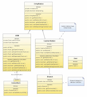
Using Class Diagrams
Classes define the attributes that are carried by each element instance and the operations that each element performs or undergoes. When representing a class in a UML model, you can do the following tasks:
- Create the element representing the class
- Name the class
- Define class attributes
- Define class operations
- Depict links and associations
- Add documentation

If a procedure is labeled as optional, it is included to illustrate an additional task or alternate way of doing a task. You do not need to do the optional procedures to complete this tutorial successfully.
| ||
 and click once in the Diagram editor. This action places a Class element on the diagram.

 on the Diagram toolbar to center the diagram in the window. This button allows you to adjust the Zoom level if necessary to read labels or to make room to place more elements on the diagram.
  . The operations are represented by the operation icon
  .
.
 .
.  .
.  .
. 
 and draw a link from CashierStation to Branch.


 .
. 

Minggu, 18 April 2010
istilah dalam basis data relasional
Istilah-Istilah Pada Model Relasional Beberapa istilah penting pada model data relasional adalah;
1. Entitas/Entity
2. Attibut
3. Data Value
4. Domain
5. Rekord/Tupel
6. Tabel/Relasi
7. Derajat (Degree) Relasi
8. Kardinalitas Relasi
1. Entitas/Entity, merupakan sesuatu yang memiliki nilai/data yang, seperti orang, tempat kejadian atau konsep yang data/informasinya perlu direkam dalam lingkup pembicaraan tertentu. Pada lingkup pembicaraan Sistem Informasi Administrasi Kemahasiswaan maka entitas yang tampil diantaranya adalah Mahasiswa, Dosen, Matakuliah, transaksi KRS dan absensi kelas.
2. Attribut, merupakan sebutan untuk mewakili suatu nilai/value dari suatu entitas. Seorang mahasisawa dapat memiliki attribut-attribut seperti NIM, Nama, Jenis Kelamin, Alamat dll. Attribut dapat juga disebut sebagai Data Elemen, Data Field atau Data Item.
3. Data Value, merupakan nilai/data aktual yang disimpan pada tiap attribut. Attribut Nama Mahasiswa menunjukkan tempat data nama seorang mahasiswa disimpan, sedangkan ‘ABU YAZID’, ‘ATO’ILLAH’, ‘DIAN AJI SUKMA’ dan ‘RETNO PALUPI’, merupakan data value dari attribut Nama Mahasiswa.
4. Domain, merupakan kumpulan/himpunan nilai-nilai yang diijinkan dan dapat dimiliki oleh suatu attribut. Setiap attribut pada basisdata relasional didefinisikan pada suatu domain. Domain tidak hanya sekedar tipe data, yang terkadang beberapa domain memiliki tipe data yang sama. Masing-masing attribut dalam suatu tabel/relasi dapat berbeda, namun sebaliknya, dapat juga dua atau lebih attribut mempunyai domain yang sama.
5. Rekord/Tupel, merupakan himpunan attribut yang saling berkaitan secara logik untuk menginformasikan tentang suatu entitas secara lengkap.
6. Tabel/Relasi, merupakan kumpulan rekord/tupel sejenis yang mempunyai panjang elemen dan attribut yang sama, namun dapat memiliki data value yang berbeda-beda. Kumpulan rekord/tupel yang sejenis tersebut didefinisikan dalam sebuah nama yang uniq untuk menunjukkan keberadaannya yang berbeda (baik nama maupun kegunaannya) dengan tabel-tabel/relasi-relasi lain dalam sebuah database.
7. Derajat (Degree) Relasi, merupakan jumlah attribut yang dimiliki oleh sebuah tabel/relasi
8. Kardinalitas Relasi, merupakan jumlah rekord/tupel yang dimiliki oleh sebuah tabel/relasi. Kardinalitas relasi otomatis berubah ketika tupel relasi ditambah atau dihapus. Nilai kardinalitas adalah kondisi suatu saat dari sabuah tabel/relasi.

Minggu, 11 April 2010
CANDIDATE KEY & ALTERNATIFE KEY
• Candidate Key
adalah super key yang himpunan bagian yang sebenarnya tidak ada yang menjadi super key juga. Berdasarkan contoh super key sebelumnya, candidate key yang mungkin adalah (NPM) dan (Nama, Alamat). Atribut Nama dan Alamat dapat dijadikan candidate key jika kombinasi keduanya bisa menjadi pengidentifikasi yang unik untuk sebuah tabel relasi.
contohnya :
File Pegawai berisi attribute:
· No Induk Pegawai (NIP)
· No KTP
· Nama
· Tempat Lahir
· Tanggal Lahir
· Alamat
· Kota
Kunci kandidat disini adalah:
· No Induk Pegawai (NIP), karena unik tidak mungkin ganda.
· No KTP, karena unik tidak mungkin ganda.
· Nama, sering dipakai sebagai kunci pencarian namun tidak dapat dikatakan kunci karena sering seseorang punya nama yang sama.
· Nama + Tanggal lahir, mungkin dapat dipakai sebagai kunci karena kemungkinan sangat kecil seseorang punya nama sama yang lahir pada hari yang sama.
· Nama + tempat lahir + tanggal lahir, dapat dipakai sebagai kunci Alamat, kota (bukan kunci).
• Alternate Key
adalah candidate key yang tidak dipilih sebagai primary key. Berdasarkan contoh candidate key sebelumnya, alternate key adalah (Nama, Alamat).
definisi DDL dan DML
*Data Definition Language (DDL) adalah bahasa dalam DBMS yang digunakan untuk membuat atau mendefinisikan obyek-obyek di dalam database. Secara umum digunakan untuk membuat obyek table dan view.
Secara khusus, di dalam DBMS tertentu digunakan untuk :
Membuat trigger
Membuat stored procedure
Membuat database, index, rule, schema dll (tergantung DBMS)
Contoh sintaks DDL :
DDL untuk tabel
* Untuk membuat tabel
CREATE TABLE (
|
)
* Untuk menghapus tabel
DROP TABLE
* Untuk memodifikasi tabel
- Menambahkan kolom baru
ALTER TABLE
ADD
- Menghapus kolom
ALTER TABLE
DROP
DDL untuk view
* Untuk membuat view
CREATE VIEW AS
* Untuk menghapus view
DROP VIEW
DDL untuk trigger
* Untuk membuat trigger
CREATE TRIGGER ON TABLE ON [DELETE] [,] [INSERT] [,] [UPDATE] AS
Objek basis data yang termasuk DDL adalah :
Tabel
Tabel terdiri dari field-field atau kolom-kolom dengan tipe data tertentu dan baris-baris yang digunakan sebagai penyimpan data.
Contoh : tabel Mahasiswa yang terdiri dari field-field : NRP (primary key), Nama, Alamat, JenisKel, NIPDosen (foreign key dari field NIP pada tabel Dosen).
Sintaks DDLnya :
CREATE TABLE Mahasiswa (
NRP char(8),
Nama varchar(20) NOT NULL,
Alamat varchar(30),
JenisKel char(1) DEFAULT “L”,
NIPDosen char(9),
PRIMARY KEY (NRP),
CONSTRAINT fk_mhs_dosen FOREIGN KEY (NIPDosen) REFERENCES Dosen(NIP) ON DELETE RESTRICT ON UPDATE CASCADE ON INSERT RESTRICT
);
View
View adalah tabel bayangan. Tidak menyimpan data secara fisik. Biasanya berupa hasil query dari tabel-tabel dalam sebuah database.
Contoh : view MahasiswaPria yang diambil dari tabel Mahasiswa di mana field JenisKel = “L”.
Sintaks DDLnya :
CREATE VIEW MahasiswaPria AS
SELECT * FROM Mahasiswa WHERE JenisKel = “L”
Trigger
Trigger adalah sebuah obyek dalam database yang berupa prosedur yang merespon setiap kali terdapat proses modifikasi (insert, update, dan delete) pada tabel.
Contoh : trigger tLogUbahNilai melakukan penambahan data pada tabel LogHistoris untuk setiap penambahan / update data pada tabel PesertaKul.
Sintaks DDLnya :
CREATE TRIGGER tLogUbahNilai ON TABLE PesertaKul
FOR UPDATE, INSERT AS
INSERT INTO LogHistoris (Tanggal, Proses) VALUES (getdate(), ‘Terjadi proses perubahan data nilai’)
*DML ( Data Manipulation Language) yaitu bahasa / perintah sql yang
digunakan untuk memanipulasi data seperti menampilkan data, menambah /
mengisi data, mengubah data dan menghapus data. Yang termasuk dalam perintah
ini adalah SELECT, INSERT, UPDATE, dan DELETE.
- INSERT
Perintah INSERT digunakan untuk menambahkan / menginputkan data ke
dalam tabel. Sintak secara umum adalah seperti berikut:
INSERT INTO Nama_Tabel(Daftar_Kolom) VALUES (Daftar_Nilai)
Yang perlu diperhatikan dalam perintah insert adalah sebagai berikut:
a. Jika tipe data yang akan diinputkan berupa string / karakter (Char,
Varchar, Text) maka gunakan tanda petik tunggal untuk mengapit data
tersebut.
b. Jika tipe data numeric / angka (Int, Numeric, Decimal) maka tidak boleh
menggunakan tanda petik tunggal.
c. Jika tipe data Datetime maka gunakan petik tunggal dengan format ‘mmdd-
yyyy’ (untuk setting tanggal Inggris/Amerika) atau ‘yyyy-mm-dd’.
d. Jika data autonumber maka data tidak perlu diisi.
Ada beberapa cara penulisan sintak insert, yaitu:
a. Tanpa menyebutkan daftar kolom, dengan catatan data yang diinputkan
harus terurut sesuai dengan urutan kolom dan semua data harus diisi
kecuali untuk kolom autonumber data tidak diisikan sebab data akan diisi
oleh system secara otomatis.
Contoh INSERT tanpa menyebutkan daftar kolom:
INSERT INTO Jurusan VALUES ('S1TI','Teknik Informatika Strata
1','Ir. Abbas Ali Pangera')
b. Menyebuatkan daftar kolom yang akan diisi saja datanya dengan catatan
jumlah kolom harus sama dengan jumlah data yang akan diisikan.
Contoh:
INSERT INTO Kelas (Kode_Kelas, Nama_Kelas) VALUES ('S1TI3E','
S1 TI Semester 3')
-SELECT
Perintah SELECT digunakan untuk menampilkan data dalam tabel. Secara
umun sintaknya adalah sebagai berikut:
SELECT Daftar_Kolom FROM Nama_Tabel WHERE Kondisi ORDER
BY Kolom
Contoh :
a. Menampilkan Data Mahasiswa
SELECT * FROM Mahasiswa
Ket : Tanda asterisk ( * ) menandakan bahwa semua kolom akan
ditampilkan
b. Menampilkan Nim dan Nama Mahasiswa
SELECT NIM, Nama FROM Mahasiswa
6.3.1 SELECT Dengan Klausa WHERE
WHERE digunakan untuk membatasi hasil SELECT yang ditampilkan
sesuai kondisi yang ditentukan. Secara umum sintaknya adalah sebagai berikut:
SELECT Daftar_Kolom FROM Nama_Tabel WHERE Kondisi
a. Operator relasional
OPERATOR ARTINYA
= Sama dengan
> Lebih dari
< Kurang dari <= Lebih dari atau sama dengan >= Kurang dari atau sama dengan
<> Tidak sama dengan
Contoh :
SELECT * FROM Mahasiswa WHERE NIM =’06.11.0123’
b. Operator logika
_ OR
_ Akan menampilkan data jika salah satu atau lebih syarat
terpenuhi.
Contoh :
SELECT * FROM Mahasiswa WHERE NIM = ’06.11.0123’ OR
Agama = ‘Islam’
_ AND
_ Akan menampilkan data jika semua syarat terpenuhi.
Contoh :
SELECT * FROM Mahasiswa WHERE NIM = ’06.11.0123’ AND
Agama = ‘Islam’
_ NOT
_ Akan menampilkan data yang sebaliknya (negasinya)
Contoh :
SELECT * FROM Mahasiswa WHERE NOT NIM = ’06.11.0123’
- DISTINCT
DISTINCT digunakan untuk menampilkan data secara unik artinya data
yang sama hanya akan ditampilkan satu kali saja.
Sintak : SELECT DISTINCT [Kolom] FROM Table
Contoh : SELECT DISTINCT NIM FROM KRS
- BETWEEN Dan NOT BETWEEN
BETWEEN digunakan untuk menampilkan data dalam nilai range tertentu
(diantaranya). BETWEEN hanya perlaku pada bilangan dan tanggal.
Sintak : SELECT [Daftar_Kolom] FROM Table WHERE Kondisi BETWEEN
Batas_Bawah AND Batas_Bawah
Contoh : SELECT * FROM Penagajar WHERE Id_Mengajar BETWEEN 2
AND 5
- TOP
TOP digunakan untuk menampilkan beberapa data paling atas dari hasil
perintah SELECT.
Sintak : SELECT TOP n [Daftar_Kolom] FROM Table
Contoh : SELECT TOP 3 * FROM Mahasiswa
- IS NULL Dan IS NOT NULL
IS NULL digunakan untuk menampilkan data – data null (Tidak Memiliki
Data). Null berbeda dengan 0 atau spasi.
Contoh : SELECT * FROM Mahasiswa WHERE Alamat IS NULL
- ORDER BY
ORDER BY digunakan untuk mengurutkan data dari hasil perintah
SELECT. Pengurutan dapat dilakukan secara Ascending (ASC) atau Descending
(DESC). Default-nya adalah secara ascending.
Contoh : SELECT * FROM Mahasiswa ORDER BY NIM ASC
- KOLOM ALIAS
Nama kolom hasil dari perintah SELECT dapat diganti namanya.
Sintak : SELECT kolom1 AS Alias1, Kolom2 AS Alias2,…dst FROM Table
Contoh : SELECT NIM AS Nim_MHS, Nama AS Nama_MHS, Gender AS
[Jenis Kelamin] FROM Mahasiswa
Secara khusus, di dalam DBMS tertentu digunakan untuk :
Membuat trigger
Membuat stored procedure
Membuat database, index, rule, schema dll (tergantung DBMS)
Contoh sintaks DDL :
DDL untuk tabel
* Untuk membuat tabel
CREATE TABLE
)
* Untuk menghapus tabel
DROP TABLE
* Untuk memodifikasi tabel
- Menambahkan kolom baru
ALTER TABLE
ADD
- Menghapus kolom
ALTER TABLE
DROP
DDL untuk view
* Untuk membuat view
CREATE VIEW
* Untuk menghapus view
DROP VIEW
DDL untuk trigger
* Untuk membuat trigger
CREATE TRIGGER
Objek basis data yang termasuk DDL adalah :
Tabel
Tabel terdiri dari field-field atau kolom-kolom dengan tipe data tertentu dan baris-baris yang digunakan sebagai penyimpan data.
Contoh : tabel Mahasiswa yang terdiri dari field-field : NRP (primary key), Nama, Alamat, JenisKel, NIPDosen (foreign key dari field NIP pada tabel Dosen).
Sintaks DDLnya :
CREATE TABLE Mahasiswa (
NRP char(8),
Nama varchar(20) NOT NULL,
Alamat varchar(30),
JenisKel char(1) DEFAULT “L”,
NIPDosen char(9),
PRIMARY KEY (NRP),
CONSTRAINT fk_mhs_dosen FOREIGN KEY (NIPDosen) REFERENCES Dosen(NIP) ON DELETE RESTRICT ON UPDATE CASCADE ON INSERT RESTRICT
);
View
View adalah tabel bayangan. Tidak menyimpan data secara fisik. Biasanya berupa hasil query dari tabel-tabel dalam sebuah database.
Contoh : view MahasiswaPria yang diambil dari tabel Mahasiswa di mana field JenisKel = “L”.
Sintaks DDLnya :
CREATE VIEW MahasiswaPria AS
SELECT * FROM Mahasiswa WHERE JenisKel = “L”
Trigger
Trigger adalah sebuah obyek dalam database yang berupa prosedur yang merespon setiap kali terdapat proses modifikasi (insert, update, dan delete) pada tabel.
Contoh : trigger tLogUbahNilai melakukan penambahan data pada tabel LogHistoris untuk setiap penambahan / update data pada tabel PesertaKul.
Sintaks DDLnya :
CREATE TRIGGER tLogUbahNilai ON TABLE PesertaKul
FOR UPDATE, INSERT AS
INSERT INTO LogHistoris (Tanggal, Proses) VALUES (getdate(), ‘Terjadi proses perubahan data nilai’)
*DML ( Data Manipulation Language) yaitu bahasa / perintah sql yang
digunakan untuk memanipulasi data seperti menampilkan data, menambah /
mengisi data, mengubah data dan menghapus data. Yang termasuk dalam perintah
ini adalah SELECT, INSERT, UPDATE, dan DELETE.
- INSERT
Perintah INSERT digunakan untuk menambahkan / menginputkan data ke
dalam tabel. Sintak secara umum adalah seperti berikut:
INSERT INTO Nama_Tabel(Daftar_Kolom) VALUES (Daftar_Nilai)
Yang perlu diperhatikan dalam perintah insert adalah sebagai berikut:
a. Jika tipe data yang akan diinputkan berupa string / karakter (Char,
Varchar, Text) maka gunakan tanda petik tunggal untuk mengapit data
tersebut.
b. Jika tipe data numeric / angka (Int, Numeric, Decimal) maka tidak boleh
menggunakan tanda petik tunggal.
c. Jika tipe data Datetime maka gunakan petik tunggal dengan format ‘mmdd-
yyyy’ (untuk setting tanggal Inggris/Amerika) atau ‘yyyy-mm-dd’.
d. Jika data autonumber maka data tidak perlu diisi.
Ada beberapa cara penulisan sintak insert, yaitu:
a. Tanpa menyebutkan daftar kolom, dengan catatan data yang diinputkan
harus terurut sesuai dengan urutan kolom dan semua data harus diisi
kecuali untuk kolom autonumber data tidak diisikan sebab data akan diisi
oleh system secara otomatis.
Contoh INSERT tanpa menyebutkan daftar kolom:
INSERT INTO Jurusan VALUES ('S1TI','Teknik Informatika Strata
1','Ir. Abbas Ali Pangera')
b. Menyebuatkan daftar kolom yang akan diisi saja datanya dengan catatan
jumlah kolom harus sama dengan jumlah data yang akan diisikan.
Contoh:
INSERT INTO Kelas (Kode_Kelas, Nama_Kelas) VALUES ('S1TI3E','
S1 TI Semester 3')
-SELECT
Perintah SELECT digunakan untuk menampilkan data dalam tabel. Secara
umun sintaknya adalah sebagai berikut:
SELECT Daftar_Kolom FROM Nama_Tabel WHERE Kondisi ORDER
BY Kolom
Contoh :
a. Menampilkan Data Mahasiswa
SELECT * FROM Mahasiswa
Ket : Tanda asterisk ( * ) menandakan bahwa semua kolom akan
ditampilkan
b. Menampilkan Nim dan Nama Mahasiswa
SELECT NIM, Nama FROM Mahasiswa
6.3.1 SELECT Dengan Klausa WHERE
WHERE digunakan untuk membatasi hasil SELECT yang ditampilkan
sesuai kondisi yang ditentukan. Secara umum sintaknya adalah sebagai berikut:
SELECT Daftar_Kolom FROM Nama_Tabel WHERE Kondisi
a. Operator relasional
OPERATOR ARTINYA
= Sama dengan
> Lebih dari
< Kurang dari <= Lebih dari atau sama dengan >= Kurang dari atau sama dengan
<> Tidak sama dengan
Contoh :
SELECT * FROM Mahasiswa WHERE NIM =’06.11.0123’
b. Operator logika
_ OR
_ Akan menampilkan data jika salah satu atau lebih syarat
terpenuhi.
Contoh :
SELECT * FROM Mahasiswa WHERE NIM = ’06.11.0123’ OR
Agama = ‘Islam’
_ AND
_ Akan menampilkan data jika semua syarat terpenuhi.
Contoh :
SELECT * FROM Mahasiswa WHERE NIM = ’06.11.0123’ AND
Agama = ‘Islam’
_ NOT
_ Akan menampilkan data yang sebaliknya (negasinya)
Contoh :
SELECT * FROM Mahasiswa WHERE NOT NIM = ’06.11.0123’
- DISTINCT
DISTINCT digunakan untuk menampilkan data secara unik artinya data
yang sama hanya akan ditampilkan satu kali saja.
Sintak : SELECT DISTINCT [Kolom] FROM Table
Contoh : SELECT DISTINCT NIM FROM KRS
- BETWEEN Dan NOT BETWEEN
BETWEEN digunakan untuk menampilkan data dalam nilai range tertentu
(diantaranya). BETWEEN hanya perlaku pada bilangan dan tanggal.
Sintak : SELECT [Daftar_Kolom] FROM Table WHERE Kondisi BETWEEN
Batas_Bawah AND Batas_Bawah
Contoh : SELECT * FROM Penagajar WHERE Id_Mengajar BETWEEN 2
AND 5
- TOP
TOP digunakan untuk menampilkan beberapa data paling atas dari hasil
perintah SELECT.
Sintak : SELECT TOP n [Daftar_Kolom] FROM Table
Contoh : SELECT TOP 3 * FROM Mahasiswa
- IS NULL Dan IS NOT NULL
IS NULL digunakan untuk menampilkan data – data null (Tidak Memiliki
Data). Null berbeda dengan 0 atau spasi.
Contoh : SELECT * FROM Mahasiswa WHERE Alamat IS NULL
- ORDER BY
ORDER BY digunakan untuk mengurutkan data dari hasil perintah
SELECT. Pengurutan dapat dilakukan secara Ascending (ASC) atau Descending
(DESC). Default-nya adalah secara ascending.
Contoh : SELECT * FROM Mahasiswa ORDER BY NIM ASC
- KOLOM ALIAS
Nama kolom hasil dari perintah SELECT dapat diganti namanya.
Sintak : SELECT kolom1 AS Alias1, Kolom2 AS Alias2,…dst FROM Table
Contoh : SELECT NIM AS Nim_MHS, Nama AS Nama_MHS, Gender AS
[Jenis Kelamin] FROM Mahasiswa
Senin, 01 Maret 2010
FIBONACCI SEARCH
Pada awalnya deret Fibonacci ditemukan oleh Leonardi
Pisano atau lebih dikenal dengan sebutan
Leonardo Fibonacci (diturunkan dari Filius
Bonaccio atau anak dari Bonaccio, sebutan bagi
ayahnya yang bernama asli Guglielmo), pada
abad 12 di Italia. Pada dasarnya deret fibonacci
merupakan barisan bilangan sederhana dimulai
dari 0 dan 1 dan suku berikutnya merupakan
jumlah dua bilangan sebelumnya. Deret
fibonacci bersifat rekursif karena menggunakan
suku dalam deret tersebut untuk menghitung
suku setelahnya.
Dengan pengertian tersebut, maka suku-suku
pada deret fibonacci adalah:
0 1 1 2 3 5 8 13 21 34 55 89 144 dan seterusnya.
KEYWORD : FIBONACCI, SEARCH, FIBO
JURNAL : FIBONACCI SEARCH
Langganan:
Postingan (Atom)